LAM, with the support of CNES, launched a Nano-satellite development program in 2013 over several years, involving several classes of students (AMU and engineering schools) from different disciplines, industrialists, as well as Radio Amateurs.
-
Nanosat student program since 2013
The Marseille Astrophysics Laboratory (LAM), with the help of the National Center for Space Studies (CNES), has launched a student Nano-satellite project.
This LAM initiative offers students the opportunity to develop a space project, from mission analysis to the exploitation of the Nano-satellite and its payload (on-board experience).
This Nano-satellite program started with a Nanosat payload call and, among three experimental proposals received, the project has continued since 2013 with the study of the South Atlantic Magnetic Anomaly (SAA) , located above of Brazil, which we propose to CArtograph .
This first Nano-Satellite project for Marseille students is planned for launch in 2024 , and has been called CASAA-Sat , CArtography of the SAA.
Placed in orbit a few hundred kilometers from Earth, it will rotate 14 times a day and communicate its measurements to us. The objective of CASAA-Sat is to:
- measure the flow of charged particles by flying over the area of interest
- measure the magnetism in this area
- photograph light phenomena , particularly at the poles
- correlate all of these measurements to try to better understand this anomaly (the SAA) and what’s more,
it is very educational!
A whole range of techniques, such as satellite attitude orbital stability control (AOCS), energy management, thermal, mechanical, electronic modeling, etc., are studied and integrated into the various student training courses.
The organization put in place for CASAA-Sat involves students in MASTERS and the IUT of Aix-Marseille University (AMU), and students in specialized engineering schools (ISAE group, ESEO, etc.) .
More than 200 students have already worked on CASAA-Sat during part-time tutored projects or full-time end-of-studies internships (2 to 6 months).
The launch of CASAA-Sat will be carried out as a passenger on a launcher and will use a polar sun-synchronous orbit at a few hundred kilometers altitude, which will pass over Brazil, the area where the anomaly is most prevalent.
Where are we ?
- The mission analysis, Phase 0, of CASAA-Sat was carried out from March to September 2013 and demonstrated that the program is realistic.
- Feasibility, Phase A, consolidated various points from Phase 0 and was carried out during 2013-2014.
- At the start of the 2014-2015 school year, we started Phase B, with the objective of preliminary defining the flight-oriented design.
- At the start of the 2015-2016 school year, we consolidated various points and the CNES established with the University of Aix-Marseille through the LAM , an agreement and a timetable allowing development to continue.
- At the start of the 2016-2017 school year, our objectives were to start Phase C/D and begin the first representative realizations of the Flight Model
and,
we will continue the design and the test phases prior to launch….
-
More info on the program and some others
Manager:
- Bernard REPETTI,
Marseille Nanosat Student Project Manager,
Research Engineer at LAM,
e-mail: bernard.repetti_at_lam.fr / Tel. : 04.91.05.69.00
A Student Space Center is available to students at LAM .
- CASAA-Sat in Phase 0/A :
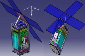
CASAA-Sat is 2U standard : 10 x 10 x 20 cm, or 2 liters.
We see an outline of the Airbrakes (sky blue) because the initial orbit chosen (METOP-C, 817 km) did not allow compliance with the Law on Space Objects (LOS) requiring re-entry into the atmosphere in less than 25 years .
CASAA-Sat at the start of Phase B
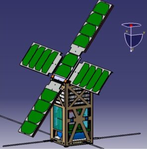
The airbrakes are still present because we had not yet changed orbit but the structure and location of the elements are better defined.CASAA-Sat at the end of Phase B
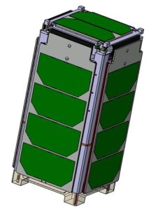
The Nanosat is shown above ready to be inserted into its launcher (solar panels closed)…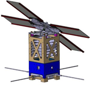
Here, the panels are open and tilted, the antennas deployed. There are no longer air brakes because we no longer plan to launch into the orbit of METOP-C but into that of PRISMA. At less than 700 km, the satellite will enter the atmosphere in less than 25 years without airbrakes…..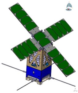
The implementations are now optimized…..The 3 components of the initial Payload are
A dosimeter, a camera and a magnetometer
A special mention for the dosimeter:
- it is a MOSFET developed by the company TRAD-Space in Labège ;
- its threshold voltage increases with the doses deposited;
- it is very small and consumes only when reading it.
It’s a simple (but very effective) way to get a good idea of the doses deposited…. If you have any questions, do not hesitate to contact TRAD-Space: www.trad.fr
- The “REER” circuit, complementary component of the Payload :
It is a circuit from ST-Micro, which integrates a memory manufactured by joint laboratories including IM2NP , a laboratory participating in the project.
The REER circuit will be installed on CASAA-Sat, and its resistance to irradiation will be tested in orbit.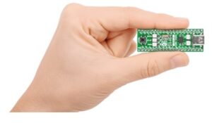
- Bernard REPETTI,
-
The STM, the mechanical model of the satellite structure
At the start of the 2017 school year:
the STM (structural mechanical model) was built:
We are embarking on the manufacture of the STM , the first model representative of the mechanical structure…..
That we are going to make and make vibrate … fingers crossed!!
- The electronic boards were simulated by epoxy plates, connectors and weights. They were stacked and an acceleration sensor was glued in to control the vibrations…
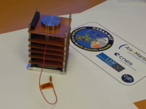
- All the boards are inserted into the upper cage of CASAA-Sat…
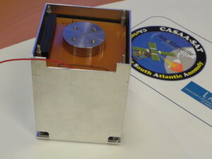
- The lower cage, which integrates the camera, the dosimeter supports and the inertia wheel (simulated by an aluminum cube on the left wall), will mate with the previous cage…
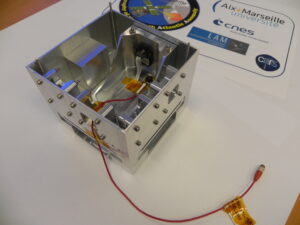
- The solar panels, which revolve around Maeva hinges with the cap which tilts by 35°, will complete the assembly of the CASAA-Sat STM…
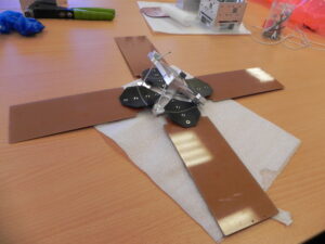
- It’s almost done…
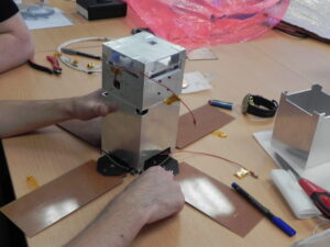
- The panels will open…
Video Player00:0000:00- We put CASAA-Sat in the ISI-Pod, launcher interface, and everything on the vibrating pot…
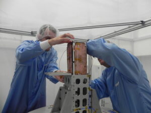
- And here is a little extract when we vibrate in X…
Video Player00:0000:00- And another when we vibrate in Z…
Video Player00:0000:00-
Everything is fine !!
The stress levels of the VEGA launcher did not fault the STM: the mechanical design of the flight model that will be launched, the FM , will therefore be identical.
Congratulations to all !!
and THANK YOU to all the students who participated in the design of this model, thank you:
- to students of the Aeronautics and Space Master’s degree, having developed CAD. The list is long but we can cite Florian, Saïd, Pape… in full-time internship at the CSE, and all those who participated in this CAO during first semester projects
- to the students of the ICPI Master, and in particular to Etienne, who is the last to have “suffered” on the STM…!
- to industrial subcontracting for the creation of these magnificent pieces
- to the mechanical department of the LAM, who helped us a lot with the assembly
- to the management of the LAM who “welcomed” CASAA-Sat on the vibrating pot
- and to Philippe, our vibration engineer at LAM!!
and the rest ,
now that the STM is validated, it is time to start working on the electronics and the Engineering Model, the EM….
-
The Engineering Model (EM), the electronic model of the satellite
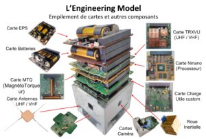
It is now the satellite’s electronics that must be assembled, tested and validated. This will materialize through the EM, which will evolve little by little. The electronics of the final model of the satellite, the FM flight model, will be composed of elements almost identical to those used for the EM.
Below is a full representation of the EM:
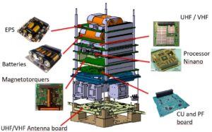
On the upper part of the structure, the EM is made up of 6 stacked electronic boards, from top to bottom:
- the 2 boards which ensure, with solar panels, the management and storage of energy
- the communication board for the satellite’s onboard/ground connection
- the “heart” of the satellite, the on-board intelligence, the OBC (On Board Computer)
- the Magnetocouplers board , which partly allows satellite attitude control (AOCS)
- and finally, the Payload and Platform management board, CU and PF board , which manages the dosimeters and ensures various connections.
Some special mentions should be made:
- The CU and PF board cannot be found “on the shelf”. It was completely designed and developed “tailor-made” by the project team.
In addition to managing the dosimeters, it provides the interface with the various components integrated in the lower part of the structure: the camera, the REER circuit to be tested, the inertia wheel (AOCS), the deployable antennas and the thermal knives (all at the bottom of the satellite) for opening the solar panels.
This board is the culmination of several study subjects: a big thank you to the students of the ConSept Pro Electronic License in Marseille Saint Jérôme!!
The list of students is long but we can mention Omar, Gaëtan… in internship at the CSE and Hector, who produced this board in 8 layers: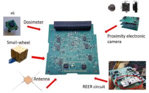
- The camera , kindly provided by CNES, is controlled by electronics also developed by the project team. A stack of 3 boards housed in the lower structure of the satellite is shown below:
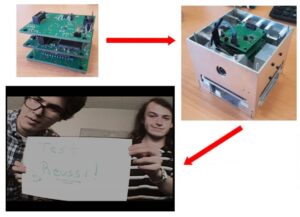
Thanks to Hector for this achievement!
Without forgetting Olivier, for carrying over the tiny components and his patience,
And Jean-Luc, for lending his equipment.And Thanks to Josue, little computer genius!, for the implementation in VHDL of an image detection code in the FPGA and an image compression routine in the OBC board (gain of a factor 30 without any loss!)
- The AOCS, after several study subjects entrusted to students of the Master 2 Aeronautics and Space, was continued by Antony and will be implemented in the OBC board. Thank you Pape, Saïd, Islem… and Antony!
- The thermal model of the satellite was also the subject of several study subjects and it resulted in the complete study under ESATAN-TMS, thank you Antony!
It will not be necessary to heat but to evacuate the calories through a thermal braid towards a cold side of the satellite….. This will however have to be verified experimentally in a thermal vacuum chamber soon.
- The flight software is to be implemented in the OBC board, it will ensure the sequencing and monitoring of all components: a heavy work already undertaken and to be continued….
It will take into account the information received by the ground station (TC, telecommand) and those to be transmitted to it (TM, telemetry).
- The ground station will be based on VHF communication for the uplink, and UHF for the downlink.
Thanks to Laurent for his investment in the equipment of on-board/ground communication!
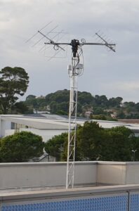
In a short time, a motorized antenna will be installed on the roof of the LAM, ground resources will be implemented, and a pointing, tracking and TM/TC plan will be implemented…..
-
End of Phase C
And yes…. the pandemic in 2020 has been there, for us too:
- Thanks to Gabriel, from ESEO Angers SE, who was still able to start the Flight Software
- And thanks also to Nathan, from ESTACA in Paris, who was able to optimize, among other things, the AOCS, the orbital alignment, the CAD, the energy collection conditions in orbit….
And in 2021, a very big thank you to:
- Clément-Bastien and Rémi, from ISAE-ENSMA Informatique et Avionique de Poitiers , who were able to consolidate the Flight Software, perfectly initiate all the work to be continued by setting up a calculation node and a Web server, the Control Center and the Mission Center of the CASAA-Sat ground station.
- The corresponding “Hardware”: the supporting structure and the first version of the motorized antennas, mounted on the roof of the LAM, and the associated SDR (Software Defined Radio) transmission chain, well done!
- and also a big thank you to Quentin, from ESEO Angers OC , who took care of all the “small” electronic problems, optimized, redesigned the boards, developed the low-level drivers, and many other things. !
The final EM assembly, below, provides an overview of the Flight Model (FM) electronics,
it will be almost identical, and all the functionalities have been tested.
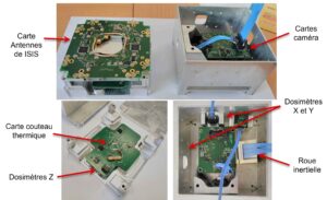
Everything is now ready to get started with the FM!
The critical review at the end of Phase C, the RCD, went very well in July 2021 in front of CNES experts.
We continue in Phase D of creating the FM flight model of the satellite : electronics & on-board computing, and mechanical structure.Everything will be tested for reliability, and must pass environmental tests…
And at the same time, we are also continuing the development of the Ground Station with Radio Amateurs.
There is still work, a lot of work!!!
-
The Ground Station
The development of the ground station began in 2016 with an internship which made it possible to realize the difficulties. It was continued by the integration of the satellite pointing software, which uses NORAD (satellite identification by NASA) which delivers orbital informations and makes it possible to actually locate the satellite. This information are used to move the motorized antennas towards the satellite as soon as it appears.
The Ground Station is the lifeline of the satellite, optimization with measuring equipment is essential.
Its implementation is not easy, given the very weak signal delivered by the satellite.
Ground radio equipment is classic, easily accessible from resellers of professional radio equipment and/or Radioamateurs, it must be installed correctly by “knowledgeable people”!
And it was at that moment that we discovered the world of amateur radio electronics engineers with important laboratories in HF measurements, without which we would not have been able to calmly wait for the future passage of our satellite.
Currently, we receive the amateur radio beacon / 432.420 MHz from Mont Cerdagne, in department 66, which is located 283km away!!
A special mention for Christophe MERCIER (Xtophe), president of AMSAT-Francophone, who introduced us to Jean-François IOSCA (callsign: F1LVO) and Fabien PELLET (callsign: F4CTZ), Radio enthusiasts and whom we thank very much .
Thanks to them and their radio knowledge, we were able to develop, implement and test the ground station, the final hardware equipment of which is presented below. This hardware is structured around digital processing, SDR: Software Defined Radio.
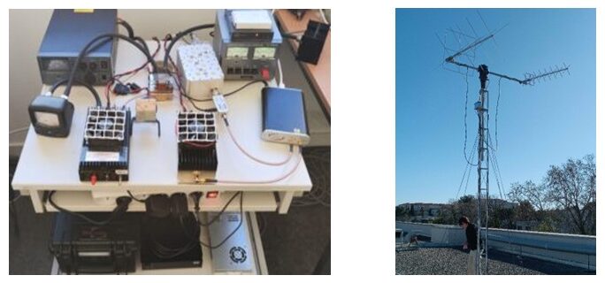
The communications that we have planned with CASAA-Sat, upstream in VHF for remote controls (TC) and downstream in UHF for telemetry (TM), will essentially be carried out with our ground station.
But, we also plan to expand communications with interested Radio amateurs who will be able, whatever their origin on the globe (IARU link), to send a TC and obtain the response in return.
For example, we will be able to send back the last image of the poles, and hopefully of an aurora borealis, if the energy on board is sufficient. If the energy risks being faulty, we can always send back the state of the satellite (temperature, voltage, etc.).
And thanks to this opening, we will be able to cover more regions of the world and better control and exploit our Nanosatellite.
It is hoped that the launch of the satellite and the associated media coverage will also make it possible to strengthen the already existing links with Radio Amateurs and to create a local Radio Club, within which Marseille enthusiasts will be able to meet and exploit CASAA-Sat, which will offer it Ground Station redundancy.
In a short time, software that manages TCs and TMs will be available here to be downloaded, installed on a PC and ready to be used, from anywhere in the world, to communicate with CASAA-Sat. -
Final phase of FM production
Where are we today…?
This Phase D will lead to the final Flight Model , which will be tested, validated and entrusted to the launcher.
Many verifications, tests, optimization, RF transmission tests with the ground station are underway,
with Quentin, who is (fortunately!) still with us, and Ahmed from ISAE-ENSMA,
and this, before developing environmental testing procedures…..
A little history…
Before presenting the latest work carried out for the Ground Station and the CASAA-Sat Thermal Vacuum tests,
and now that the satellite is almost finished, just a little reminder:
more than 200 students were involved in this project , from Bac+2 to Bac+5 level, in internships in different specialties or in tutored projects,
around thirty of whom (photo below) carried out their PFE, End of Study Project, for 6 months full-time at LAM.
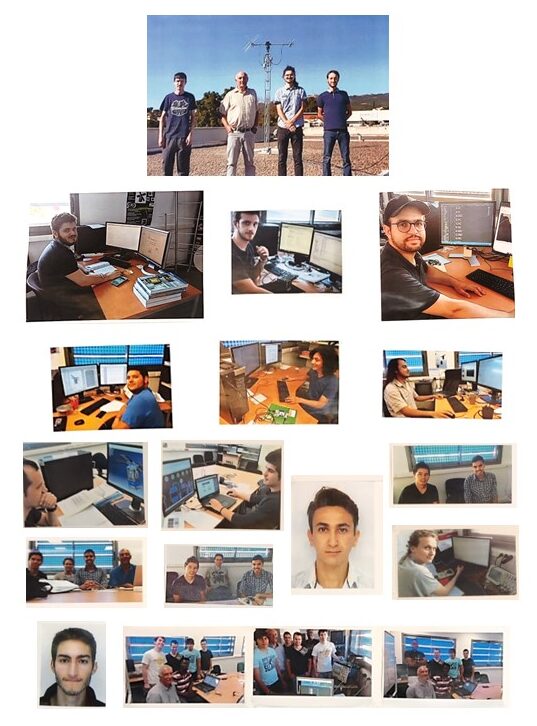
They all made their contribution, a big thank you to them!!
And also, a very big thank you to all the teacher-researchers and training managers,
and more particularly to Alain GARINO and Fabrice AUBEPART .
To complete the team, and until the launch (scheduled for mid-2024), we always welcome very motivated interns.
Here is the internship profile that would best suit our needs:
Internship_Software_Engineer_2023
- Thermal Vacuum Tests
The Thermal Vacuum test equipments make it possible to reproduce the orbital constraints that the satellite will have to withstand: vacuum and temperatures. An orbit at 600 km lasts on average around a hundred minutes, a third of which is in eclipse: we subjected CASAA-Sat to cycles ranging from +50°C to -50°C for several hours. This required several adaptations for the preparation of the satellite, but also for the testing resources as well as a lot of time to devote during cycling to follow developments.
We would like to thank very much:
- the LAM Management, for allowing us to carry out these tests
- Christophe and Michaël, responsible for these testing
- Manu and Patrick, for the time spent with us on our issues
- Johan, for the bondings that were necessary
- Patrick and José, for mechanical services in mechanics
- Marc, Laurent, Benjamin, Anne-Sophie, Tangui, Kacem, and many other people from LAM, for their help and support in different areas
- Nicolas, Rémi, Gilles, Anton, Dephine, Stéphane and Paul from CNES Toulouse, for their valuable help and advice throughout the development of this FM
and without forgetting all the manufacturers and partners!
These tests, spread over several weeks, were completely successful. Below we can see the CASAA-Sat Flight Model, fully equipped with Flight boards and components, also equipped with several temperature probes and placed in an isolated box, the MCT (Cryogenic and Thermal Medium), inserted in a vaccum chamber.
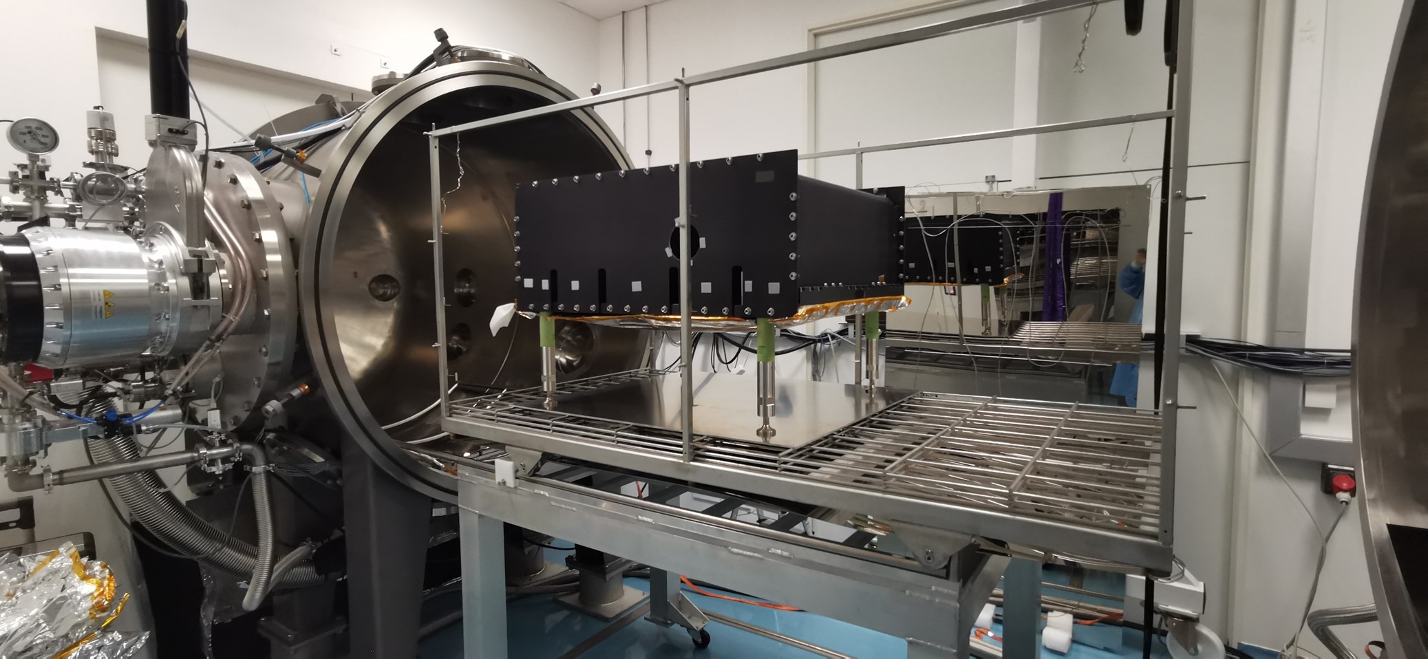
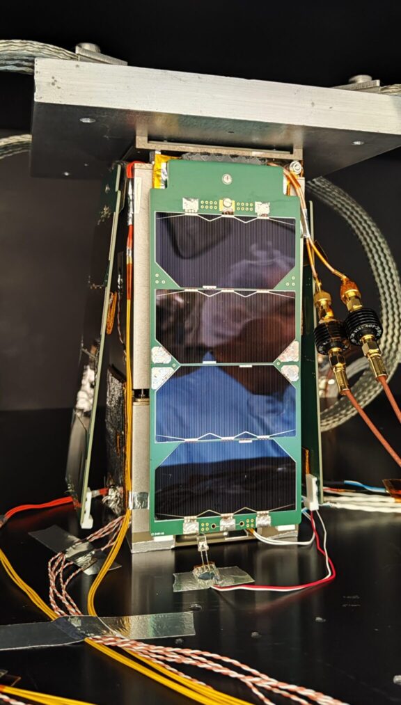
CASAA-Sat has successfully undergone the various tests of all of its components and also the long-awaited tests for opening the solar panels!
…….
-
Le lanceur
…
-
Les formalités administratives
…
-
L'intégration sur le site de lancement
…


